Home
/ 555 Timer Circuit Schematic, Quick 555 timer astable multivibrator mode circuit ... - The lm555 has a maximum typical supply voltage rating of 16v while the relay's armature coil is enabled at 12v.
555 Timer Circuit Schematic, Quick 555 timer astable multivibrator mode circuit ... - The lm555 has a maximum typical supply voltage rating of 16v while the relay's armature coil is enabled at 12v.
555 Timer Circuit Schematic, Quick 555 timer astable multivibrator mode circuit ... - The lm555 has a maximum typical supply voltage rating of 16v while the relay's armature coil is enabled at 12v.. We can see that it us made up of 21 transistors, 4 diodes, and 15. Learn about the 555 timer and how it works in astable mode. This 555 timer is in astable mode. It's a simple source of oscillating in the schematic above, notice that the threshold pin and the trigger pin are connected to c1. One configuration of this timer creates a perfect square wave.
The 555 timer can provide time delays ranging from several minutes for one cycle of operation to many. Timer b in this method acts as a voltage comparator and has no timing function. This cycles 60 times every second. In this circuit, we will build a clock of about 60hz. The 555 and 7555 are called timers or timer chips.
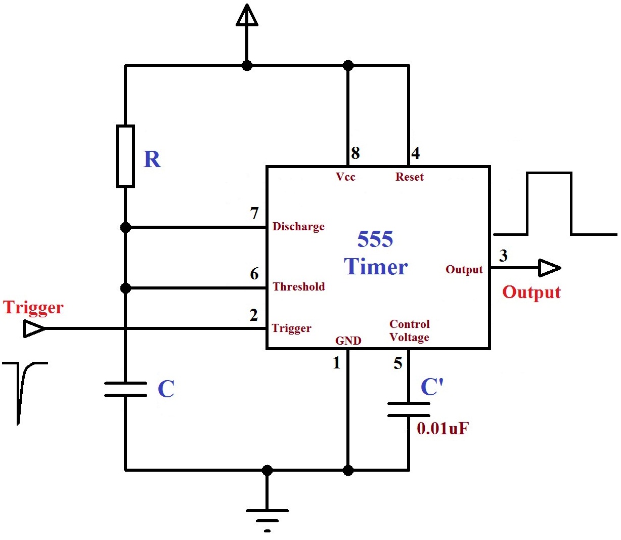
Monstable Multivibrator using 555 Timer from electrosome.com Before drawing the schematic, we need to create a library where we need to create and store the symbols for components. The breadboard schematic of the above circuit is shown below. And now a full schematic of the 555 timer oscillator with single step and free run option. The timer generates an output pulse with an on time period determined by the rc network i.e t = 1.1rc. The 555 timer is a simple integrated circuit that can be used to make many different electronic circuits. With this information you will learn how how the 555 works and will have the experience to build some of the circuits below. This is the schematic below for the 555 timer that creates one square wave output. The lm555 has a maximum typical supply voltage rating of 16v while the relay's armature coil is enabled at 12v.
Monostable 555 timer circuits will automatically trigger and start a timing cycle when power is applied to the circuit.
Due to its relative simplicity, ease of use and low cost it has been used in literally thousands of applications for standard 555 timers use timing resistor values between 1k ohms and 1m ohms. The output load is driven by the relay switch which is in turn controlled by the timer circuit. The standard 555 timer ic is used in a variety of timer, pulse generation and oscillator applications. 555 ic automatically switches back to stable state after some time, this time, for which the 555 stays in quasi stable state, is determined by the time constant of rc network in the circuit. These are easy to build 555 circuits for beginners and advanced engineers. This is the schematic below for the 555 timer that creates one square wave output. Typical schematics in monostable operation. The schematic is shown in fig 5. The timer generates an output pulse with an on time period determined by the rc network i.e t = 1.1rc. The good thing is that this chip could work directly with 12v so no driver for the mosfet is needed. I used a 9v supply and battery snap for my circuit. The 555 timer can provide time delays ranging from several minutes for one cycle of operation to many. You can watch the following video or read the written tutorial below.
It's a simple source of oscillating in the schematic above, notice that the threshold pin and the trigger pin are connected to c1. The red section is the. Si notation all the schematics in this ebook have. Timer b in this method acts as a voltage comparator and has no timing function. We can see that it us made up of 21 transistors, 4 diodes, and 15.
555 timer IC - Wikipedia from upload.wikimedia.org Taking apart a circuit board or module and reconstructing its complete schematic is a valuable skill. The output of uc (upper comparator) which is reset input to rs latch is high when the threshold input is high or. It's a simple source of oscillating in the schematic above, notice that the threshold pin and the trigger pin are connected to c1. The 555 timer, designed by hans camenzind in 1971. The 555 and 7555 are called timers or timer chips. These fifteen 555 timer circuits are simple to make with widespread usability. The red section is the. Over 100 of 555 timer circuits and projects including the ic datasheet.
This is the schematic below for the 555 timer that creates one square wave output.
To observe the 555 timer in astable mode, let's build a circuit that uses the 555 timer's oscillating output to make. I used a 9v supply and battery snap for my circuit. 555 ic automatically switches back to stable state after some time, this time, for which the 555 stays in quasi stable state, is determined by the time constant of rc network in the circuit. To make the same circuit as mentioned above without ic 555 timer, we will have to use the following basic electronic components and devices. Astable mode can produce digital square waveforms that go back and forth between. The lm555 has a maximum typical supply voltage rating of 16v while the relay's armature coil is enabled at 12v. Si notation all the schematics in this ebook have. The 555 and 7555 are called timers or timer chips. Due to its relative simplicity, ease of use and low cost it has been used in literally thousands of applications for standard 555 timers use timing resistor values between 1k ohms and 1m ohms. You can watch the following video or read the written tutorial below. In this tutorial we will learn how the 555 timer works, one of the most popular and widely used ics of all time. This 555 timer is in astable mode. Monostable circuit example figure 6 shows a complete 555.
Learn about the 555 timer and how it works in astable mode. • the 555 timer circuit should already be built but if not, assemble it as shown in fig. The 555 timer can provide time delays ranging from several minutes for one cycle of operation to many. Clap switch circuit using ic 555 timer & without timer. We can see that it us made up of 21 transistors, 4 diodes, and 15.
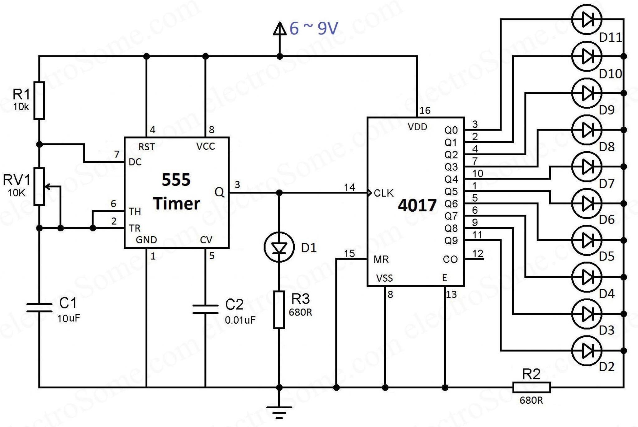
LED Chaser using 4017 Counter and 555 Timer from electrosome.com Each component has the schematic symbol and a label printed on. Monostable 555 timer circuits will automatically trigger and start a timing cycle when power is applied to the circuit. The 555 timer ic has found widespread use in a variety of applications, and is still used widely due so we will use the 10 kω resistor and two 10 μf capacitors in the timing circuit of the 555 timer. Over 100 of 555 timer circuits and projects including the ic datasheet. Timer b in this method acts as a voltage comparator and has no timing function. Typical schematics in monostable operation. The output load is driven by the relay switch which is in turn controlled by the timer circuit. And now a full schematic of the 555 timer oscillator with single step and free run option.
A better circuit is using a 555 timer.
Timer b in this method acts as a voltage comparator and has no timing function. Each component has the schematic symbol and a label printed on. The ne555, sa555, and se555 monolithic timing circuits are highly stable controllers capable of producing accurate time delays or oscillation. The 555 timer ic is an integrated circuit (chip) used in a variety of timer, delay, pulse generation, and oscillator applications. Since the project only involves assembling a simple circuit by following the schematic, it will only take an hour to make. The standard 555 timer ic is used in a variety of timer, pulse generation and oscillator applications. It's a simple source of oscillating in the schematic above, notice that the threshold pin and the trigger pin are connected to c1. 7 below, you'll see the circuit schematic of the 555 and the parts relevant to it. The timer's internal circuitry is largely responsible for this. Due to its relative simplicity, ease of use and low cost it has been used in literally thousands of applications for standard 555 timers use timing resistor values between 1k ohms and 1m ohms. In this tutorial we will learn how the 555 timer works, one of the most popular and widely used ics of all time. The breadboard schematic of the above circuit is shown below. The 555 timer is an integrated circuit, it is extremely versatile and can be used to build lots of different circuits.
The 555 and 7555 are called timers or timer chips 555 timer schematic. Derivatives provide two (556) or four (558) timing circuits in one package.
